
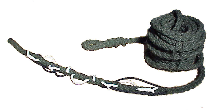
HELI-VAC™ FAST ROPE® SYSTEMS provide efficient and safe methods for
infiltrating and evacuating special operation personnel to and from point
targets.
A special low stretch, abrasion reisitant fiber, Dacron M/P Type
77* and Pli-Moor® construction eliminate rope hockling or kinking,
resist heat build up during
use, and afford fast, fully controlled descent and
safe, sure assent.
The FAST ROPE® SYSTEMS were developed in the U.S. during the mid 1980’s in a coordinated effort with our nations military and law
enforcement services.
In 1990, Columbian along with the U.S. Army Natick RD
Center in Natick, MA authored and developed the only FAST ROPE® mil-spec which
is still in use
today, Military Specification MIL-F-44422 Fiber Rope Assembly,
Insertion/Extraction.
1. SCOPE
1.1 Scope.
This specification covers a fiber rope assembly for the intended use of quick
evacuation of military personnel from rotary wing aircraft,
(Infiltration Type), or quick Extraction from a ground location by rotary wing aircraft at
various elevations.
1.2 Classification. The rope assembly’s are classified as the
following types:
HELI-VAC FAST ROPE HELICOPTER INFILTRATION & EXTRACTION SYSTEMS (OLIVE DRAB) 8
STRAND PLIMOOR
M/P TYPE 1 INFILTRATION SYSTEM HIGH TECH TERMINATION
P/N 3316662 M/P
Type I Heli-Vac System w/ High Tech Hardware Termination, 50 feet long (±10%,
-0%)
P/N 3316660 M/P Type I Heli-Vac System w/ High Tech Hardware Termination, 60
feet long (±10%, -0%) NSN: 4020-01-352-2728
P/N 3316661 M/P Type I Heli-Vac System w/ High Tech Hardware Termination, 90
feet long (±10%, -0%) NSN: 4020-01-352-2729
P/N 3316663 M/P Type I Heli-Vac System w/ High Tech Hardware Termination, 120
feet long (±10%, -0%) NSN: 4020-01-352-2730
M/P TYPE
2 INFILTRATION / EXTRACTION SYSTEM
HIGH TECH TERMINATION
P/N 3326682 M/P Type 2 Heli-Vac System w/ High Tech Hardware Termination &
Extraction Component, 50 feet long (±10%, -0%)
P/N 3326680 M/P Type 2 Heli-Vac System w/ High Tech Hardware Termination &
Extraction Component, 60 feet long (±10%, -0%)
P/N 3326681 M/P Type 2 Heli-Vac System w/ High Tech Hardware Termination &
Extraction Component, 90 feet long (±10%, -0%)
P/N 3326683 M/P Type 2 Heli-Vac System w/ High Tech Hardware Termination &
Extraction Component, 120 feet long (±10%, -0%)
M/P TYPE
3 INFILTRATION SYSTEM EYE SPICE TERMINATION
P/N 3336672 M/P Type 3 Heli-Vac System w/ Eye Splice Termination, 50 feet long
(±10%, -0%)
P/N 3336670 M/P Type 3 Heli-Vac System w/ Eye Splice Termination, 60 feet long
(±10%, -0%)
P/N 3336671 M/P Type 3 Heli-Vac System w/ Eye Splice Termination, 90 feet long
(±10%, -0%)
P/N 3336673 M/P Type 3 Heli-Vac System w/ Eye Splice Termination, 120 feet long
(±10%, -0%)
M/P TYPE
4 INFILTRATION / EXTRACTION SYSTEM
EYE SPLICE TERMINATION
P/N 3346692 M/P Type 4 Heli-Vac System w/ Eye Splice Termination & Extraction
Component, 50 feet long (±10%, -0%)
P/N 3346690 M/P Type 4 Heli-Vac System w/ Eye Splice Termination & Extraction
Component, 60 feet long (±10%, -0%) NSN: 4020-01-338-3307
P/N 3346691 M/P Type 4 Heli-Vac System w/ Eye Splice Termination & Extraction
Component, 90 feet long (±10%, -0%) NSN: 4020-01-338-3308
P/N 3346693 M/P Type 4 Heli-Vac System w/ Eye Splice Termination & Extraction
Component, 120 feet long (±10%, -0%) NSN: 4020-01-338-3309
2.0 SPECIFICATIONS
2.1 Materials.
2.1.1 Main
Line.
The main rope line shall be fabricated from virgin continuous filament, DuPont™
Type 77 Mulitplex™ Dacron Polyester constructed of heat
and light resistant
polyethylene terephthalate type polyester with a staple wrap. The rope shall be
dyed green to approximate any color in the range
indicated by color chips 34052,
34079, 34086, 34092, 34096, 34097, 34098, 34102, 34108, and 34128 of U.S.
FED-STD-595.
2.1.2 Main Line Construction.
The rope shall be
constructed of eight strands arranged in four pairs, where one individual strand
shall be laid adjacent to the second strand in each pair,
and shall conform to
the requirements specified herein and in table I. Individual strands shall be
made of one size of singles yarn and shall have an equal
number of yarns. The
yarn shall be 45000 denier, with a minimum breaking strength of 620 lbs. and
shall be “S” and “Z” twist. The rope shall be
constructed without knots or
splices in the strands of the rope. However, knots will be permitted in the
singles yarn. In preparation of the constituent
rope strands, the pattern “S”,
(or “Z”), shall be employed in the twisting of the yarns and the individual
strands of the two pairs while the components
of the remaining pairs shall be
twisted in the “S”, (or “Z”), pattern. The finished rope shall be so
constructed that in the interweaving procedure, pairs of
strands of the former
structure shall be twisted in the “Z” direction, while alternating pairs of the
latter shall be twisted simultaneously in the “S” direction.
Heat setting of
the rope or any portion of its components shall not be permitted. The physical
requirements of the Main Line rope are listed in table 1.
2.1.3 White Nylon extraction loops rope & Black Nylon Safety line rope.
The rope shall be
constructed of eight strands arranged in four pairs, where one individual strand
shall be laid adjacent to the second strand in each pair
and shall conform to
the requirements specified herein and in table I. Individual strands shall be
made of one size of balanced 3-ply yarns and shall
have equal numbers of plied
yarns. The singles yarn shall be 4000 to 10000 denier. The rope shall be
constructed without knots or splices in the singles
yarn, 3-ply yarns, strands,
or rope. Knots in the single filaments are acceptable. In the preparation of
the constituent rope strands, the pattern “SZS”
twist shall be employed in the
twisting of the singles yarns, the 3-ply yarns and the individual strands of two
pairs, while the components of the remaining
pairs shall be twisted in the “ZSZ”
pattern. The finished rope shall be so constructed that in the interweaving
procedure, pairs of strands of the former
structure shall be twisted in the “Z”
direction, while alternating pairs of the latter structure shall be twisted
simultaneously in the “S” direction.
The finished rope shall be heat set. Dry
heat setting is prohibited
TABLE I. Main Rope Physical Requirements
|
CHARACTERISTIC
|
REQUIREMENT |
|
Main Line |
1-3/4” |
|
White Nylon Extraction Line & Black Nylon Safety Line Diameter in inches 1/ |
9/16” |
|
Main Line Circumference in inches at load “P” 2/ |
5-1/2 ± Ľ” |
|
White Nylon Extraction Line & Black Nylon Safety Line Circumference in inches at load “P” 2/ |
1-3/4 ± 1/8” |
|
Main Line Load “P” (pounds) 2/ |
610 lbs. |
|
White Nylon Extraction Line & Black Nylon Safety Line Load “P” (pounds) 2/ |
65 lbs. |
|
Main Line Rope Breaking strength minimum |
35,000 lbs. |
|
White Nylon Extraction Line & Black Nylon Safety Line Breaking strength minimum |
9,000 lbs. |
|
High Tech Hardware minimum failure strength (pull out of main line weave) |
9,000 lbs. |
|
Main Line Hardness minimum/maximum (pounds) |
325 lbs. to 450 lbs. |
|
White Nylon Extraction Line Hardness minimum/maximum |
4 lbs. / 12 lbs. |
|
Black Nylon Safety Line Hardness minimum/maximum |
30 lbs. / 60 lbs. |
|
Main Line Feet per pound at load “P” 2/ |
1.23 Ft per Pound ± 5% |
|
White Nylon Extraction Line Feet per pound at load “P” 2/ |
10.79 Ft per Pound ± 5% |
|
Black Nylon Safety Line Feet per pound at load “P” 2/ |
1.034 Ft per Pound ± 5% |
|
Elongation maximum (percent) (Main Line Only) |
59% |
|
Loss in breaking strength after heat aging, not exceeding (percent) Requirement Applies to All Lines |
10% |
|
Moisture content maximum (percent) Requirement Applies to All Lines |
5% |
|
Extractable matter maximum (percent) Requirement Applies to All Lines |
4% |
1/ Not
a specification requirement; included for information only.
2/ The
load “P” (pounds) shall be equal to 200 times the square of the nominal diameter
of the rope in inches (P = 200D˛).
3.0 M/P
TYPE 1 & M/P TYPE 2 HARDWARE TERMINATION COMPONENTS
3.1 The
physical requirements of the High Tech Hardware Termination assembly are listed
in table 2.
TABLE 2. High
Tech Hardware Physical Requirements
|
COMPONENT
|
REQUIREMENT |
|
6” Steel Sleeve, Clevis, Pins |
Electroless / Cadmium / Plating IAW Mil-QQP-416 |
|
Aluminum End Cap |
Electroless / Cadmium / Plating IAW Mil-QQP-416 |
|
Oval-Ring Alloy Grade 4140 A.Q. |
Plaiting ASTM B 633 CL FEZN 12 Yellow |
|
Mounting Ring Strength |
12,000 Pound Proof Test |
|
Safety Cable |
Stainless Steel 3/16” Diameter, 7 x 19 Construction |
|
Safety Cable |
Minimum failure strength 1,000 lbs. |
4.0 INSPECTION and MAINTENANCE PROCEDURES
4.1
Suggested inspection procedures. Examine the main line for any visual
defects. If possible, lay out the entire length of line for inspection.
Minor
defects may be acceptable at the discretion of the inspector. Critical defects
require repair and/or replacement as recommended by the manufacturer.
TABLE 5.
Inspection Elements
|
EXAMINE DEFECT DEFECT CLASSIFICATION
|
|||
|
|
MINOR |
CRITICAL |
|
|
Main Line Rope |
Abraded Yarns |
X |
|
|
|
Burns |
|
X |
|
|
Cut Yarns |
|
X |
|
|
Stand Kinking |
|
X |
|
|
Whipped End Loose |
X |
|
|
|
Whipped End missing & line unraveling |
|
X |
|
|
|
|
|
|
High Tech Hdwe Termination |
Excessive wear, ring assembly |
|
X |
|
|
Missing screws |
|
X |
|
|
Rope pulling out of 6” metal sleeve |
|
X |
|
|
Safety cable slightly frayed |
X |
|
|
|
Safety cable strand broken |
|
X |
|
|
Safety cable strands separated |
|
X |
|
|
Safety cable eye-splice clamp is loose |
|
X |
4.2 Suggested maintenance. During routine inspection the following repairs can be performed.
A.
Safety Cable eye splice may be repaired by replacement of swag block by any
qualified rigging shop. The swag block should be equal in quality to the
original, Nicropress Oval Sleeve No.
168-6-VP for 3/16” Stainless Steel Cable.
B.
Loose
screws may be tightened by the user. Be sure to use the proper equipment and
lock threads with a thread locking compound equal to Loctite® 262
HIGH STRENGTH THREADLOCKER, P/N 26241
C.
Loose
whipped ends on lines may be re-whipped by a qualified rope splicer.
ALL OTHER REPAIRS MUST BE PERFORMED BY THE MANUFACTURER
4.3
Storage
Procedures
1)
If
the line is wet, hang the line full length and allow to dry before storage.
Seawater will not harm the fiber, but the line should not be stored wet.
2)
Clean
the line with an artificial, or natural hair bristle brush only. Do not use
cleaning fluids or water.
3)
Coil
the line using no less than an 18 inch coil.
4)
Store
the line in a dry area and not in contact with the ground.
5)
If
the line is not used fro an extended length of time, after 6 months of storage
uncoil the line and allow the line to hang full length for 24 hours.
6)
Re-store the line using the steps above in steps 3 and 4.